Send Message
Hot Products Top Products
About Us
China Guangdong Hua Qun Traffic Facilities Co., Ltd. By Shares
About Us
Guangdong Hua Qun Traffic Facilities Co., Ltd. By Shares
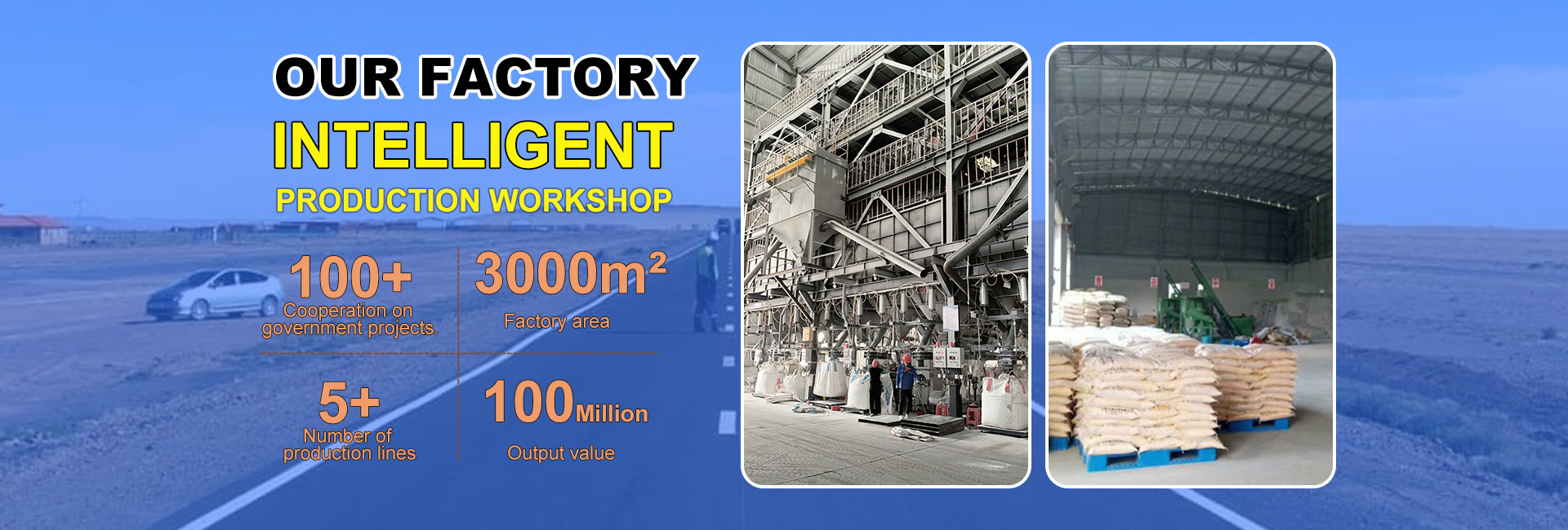
Guangdong Hua Qun Traffic Facilities Co., Ltd. By Shares was found in 2 0 1 0, there are two factories located in Guangzhou and Zhanjiang, Guangdong province. Hua Qun registered capital of 13.66million R M B, and has its own import and export right.Hua Qun is a professional manufacturer in road safety product for over 10 years, specializing in thermoplastic paint, glass beads,road marking mchine with competitive price,have cooperated with more than 100 government projects. We also provide ...
Read more
Request A Quote
0
Year
Customers
0%
P.C
WE PROVIDE
THE BEST SERVICE!
You can contact us in various ways
Contact Us
Guangdong Hua Qun Traffic Facilities Co., Ltd. By Shares

quality Thermoplastic Road Marking Paint & Road Marking Machine factory

Events
Lastest company news about ASTM E2832-2017
ASTM E2832-2017

2024-10-22

                                                        ASTM E2832-2017                                                         Standard Test Method for                Measuring the Coefficient of Retroreflected Luminance of Pavement                   Markings in a Standard Condition of Continuous Wetting (RL-2)                                                      ASTM E2832-12(2017)                                                        1. Scope     1.  Scope 1.1 This test methodcovers a measurement of the wet retroreflective (mcd/m2/lx) propertiesof horizontal pavement marking materials, such as traffic stripes and roadsurface symbols. A standardized method utilizing a standardized continuouswetting device and a portable retrorefleclometer is described to obtainmeasurements of the welretroreflective properties of horizontal pavementmarkings.   1.2 Retroreflectiveperformance obtained with this test in a standardized condition of continuouswetting does not necessarily relate to how markings perform in all conditionsof natural rain. NOTE 1—Test Method E2I77 may be used to describe theretroreflective properties of pavement markings in conditions of wetness, suchas after a period of rain.   1.3 This testmethod is suitable for measurements made in the laboratory and in the fieldwhen the necessary controls and precautions are followed.   1.4 This testmethod specifies the use of external beam retroreflectometers conforming toTest Method El710.2 Theentrance and observation angles required of the retroreflectometer in this testmethod are commonly referred to as “30 meter geomelry."2   1.5 The testmethod excludes the effects of rain between the vehicle and the marking.   1.6 Resultsobtained using this test method should not be the sole basis for specifying andassessing the wet retroreflective etfectiveness of pavement marking systems.Users should complement the results of this test method with other evaluationresults, such as nighttime visual inspections.   1.7 The valuesstated in SI units are to be regarded as standard. The values given inparentheses are for information only.   1.8 Thisstandard does not purport to address all of the safety concerns, if any,associated with its use. It is the responsibility of the user of this standardto establish appropriate safety, health, and environmental practices and determinethe applicability of regulatory limitations prior to use.   1.9 Thisinternational standard was developed in accordance with internationally recognizedprinciples on standardization established in the Decision on Principles for theDevelopment of International Standards, Guides and Recommendations issued bythe World Trade Organization Technical Barriers to Trade (TBT) Committee.                                                               2.Reference Documents   2   Referenced Documents 2.1 ASTM Standards: ASTM   El77 Practice for Use of the Terms Precision and Bias in ASTM TestMethods E691 Practice for Conducting an In ter laboratory Study to Determinethe Precision of a Test Method E965 Test Method for Measuring Pavement Macrotexture Depth Using aVolumetric Technique E1710 Test Method for Measurement of Retroreflective Pavement MarkingMaterials with CEN-Prescribed Geometry Using a Portable Retroreflectometer E2177 Test Method for Measuring the Coefficient of Ret- roreflecledLuminance (RL) of Pavement Markings in a Standard Condition of Wetness                                                                3. Terminology   3 Terminology   3.1Definitions:   3.1.1coefficient of retroreflected luminance, RL, n—the ratio of theluminance, L, of a projected surface to the normal illuminance, E, at thesurface on a plane normal to the incident light, expressed in millicandelas persquare metre per lux (mcd/nr/lx).   3.1.2conditions of continuous wetting, n—the test condition where thepavement marking specimen is subjected to continu¬ously uninterrupted waterspray applied uniformly over a pavement marking at a defined and controlledrate during measurement.   3.1.3external beam R, retroreflectomeiers, n—a pavement markingretroreflectometer that measures the coefficient of retrorefleeted luminance.RL, in a measurement area that falls entirely outside the retroreflectometer.   3.1.4 RL-2, the steadystate coefficient of retroreflected luminance, RL, determined underdefined conditions of continuous wetting at a rate of 2 inches per hour.   3.1.4.1 Discussion—The results from thistest method shall be reported as R(L.2) where "2" designates thewetting rate used in inches per hour (in./h).   3.1.5steady state conditions, n一the measurements have reached steady statewhen six consecutive retroreflectometer instrument readings made atapproximately 10s intervals show no consistent tending of the coefficient ofretroreflected luminance value up or down.                                                     4. Summary of Test Method      4.1 This test method describes a standard procedure for measuring theretroreflective properties of horizontally applied pavement marking systemsunder conditions of continuous wetting.   4.2 The pavement marking system under test is subjected to continuouswetting delivered by a wetting device of a specified design calibrated toprovide a controlled wetting rate.   4.3 A protocol andinstrument requirements are described for measuring RL_2 under a definedcondition of continuous wetting.                                                              5. Significance and Use   5.1 This test method produces a measure ofretroreflective efficiency (coefficient of retroreflected luminance, RL-2)for a pavement marking system under conditions of continuous wetting. The testresult depends on factors such as the pavement marking binder and opticmaterials, their application, wear from traffic and plowing, wetting rate, androad grade and cross slope.   5.2 The measured retroreflective efficiency underconditions of continuous wetting may be used to characterize the proper¬ties ofa pavement marking on the road as water is continuously falling on it. Theretroreflective efficiency of the marking under conditions of continuouswetting is almost always different than under dry conditions.   5.3 The wetting rate of 2 in./h represents the upper limit of what is meteorologicallyclassified as heavy rainfall. Rainfall rates above 2 in./h are classified as extreme or violent, and are sometimesassociated with weather such as tropical storms.   5.4 The retroreflectivity of pavement markingsdegrades with traffic wear and requires periodic measurement to ensure that thecoefficient of retroreflected luminance under continu¬ous wetting meetsrequirements and provides adequate visibil¬ity for nighttime drivers.   5.5 The continuous wetting rate as well as theroadway grade and cross slope impact the results of this test method. The usershall measure and report the rate used for testing.   5.6 The roadway grade and cross slope adjacent tothe measurement area impact the results of this test method. A digital level(inclinometer) can be used to quickly measure grade and cross slope.   5.7 Results obtained using this test method shouldnot be the sole basis for specifying and assessing the wet retroreflectiveeffectiveness of pavement marking systems. Users should complement the resultsof this test method with other evalua¬tion results, such as nighttime visualinspections.                                                                    6. Interferences   6.1 Newlyinstalled pavement markings may have surface properties that prevent uniformwetting. This hydrophobic condition can produce inconsistent and highlyvariable results when measuring the coefficient of retroreflected luminanceunder continuous wetting conditions.   6.1.1 It is recommended thatmeasurements be made at least 14 days after markings are applied. Hydrophobicconditions are generally eliminated by exposure to the environment and wear oftraffic.   6.1.2 For laboratory measurements ofpavement marking systems installed on panels, particular care must be taken toavoid hydrophobic conditions, since the panels are typically not exposed totraffic. The use of a surfactant in the water reservoir has created problems ofmicroscopic foaming and bubbles, resulting in unacceptable variability inreadings. More testing is needed before a specific surfactant can be recommended.                                                                      7. Apparatus   7.1 Retroreflectometer:   7.1.1 The retroreflectometer shall bean external beam RL retroreflectometer (see 3.1.3).   7.1.2 The retroreflectometer shallhave such dimensions and location of the measurement area such that theretroreflecto¬meter can be placed relative to the wetting device so that themeasurement area falls entirely within the wetted area inside the wettingdevice.   7.1.3 The retroreflectometer shallmeet the requirements of Test Method El710.   7.2 WettingDevice:   7.2.1 The wetting device shallconform to the design and operating parameters in Annex Al.   NOTE 2—Water drop size and velocity atimpact will impact retrore¬flected luminance measurements of markings. Thewetting apparatus described in Annex Al has particular water impactcharacteristics that have not been quantified. In order to measure theretroreflected luminance measurements of markings under conditions ofcontinuous wetting in a standard way. the design and construction of thewetting device described in Annex AI must be followed.                                                                        8. Reagents and Materials   8.1Clean water free of particulate and dissolvedsolids shall be used to prevent clogging of the nozzles. Commercial distilleddrinking water is recommended.                                                                        9. Sampling, Test Specimens, and Test Units                                                                                      9.1 For field measurements, the test specimensselected shall be visually representative of the pavement marking to be evaluatedand free of obvious excessive wear such as skid marks or plow damage.   9.2 Although only one test specimen is required,multiple lest specimens are recommended.   9.3 Measurements shall be recorded only aftersteady stale conditions have been achieved. Record a minimum of four instrumentreadings before moving the wetting apparatus.                                                              10. Calibration and Standardization   10.1 ExternalBeam Retroreflectometer:    10.1.1 The retroreflectometer shall bestandardized accord¬ing to the instructions from the instrument manufacturerusing the calibrated reference or working standard supplied with theinstrument.   10.1.2 Transporting portableretroreflectometers from an air conditioned area to the test site may result infogging of mirrors in the instrument. If there is any doubt concerning lhestandardization or if lhe readings of the reference or working standard are notconstant, allow the instrument to reach ambient conditions and re-standardizewith lhe reference or working standard. If the problem persists, suspend lhemea¬surements until lhe instrument can be repaired.   10.1.3 The standardization of the instrument shall be re¬verified at least onceper day under dry conditions. If the subsequent readings on the referencestandard deviate by more than five percent from the reference value,re-standardization shall be performed. If the readings on the referencestandard deviate by more than ten percent from the reference value,re-standardize and, in addition, repeat all measurements made subsequent to theprior successful verification or standardiza¬tion.   10.2 Wetting Device:    10.2.1 Calibration of the wetting rate shall be performed prior to anymeasurements. Adjust lhe nozzle angle and operating pressure until the requiredcontinuous wetting rate is achieved.   10.2.2 Center three adjacently placed dry containers of known opening area(each measuring approximately 100 inin (4 in.) wide by 100 mm (4 in.) long) over the retroreflectometer measurement area (thecontainers shall be at least 12.5 mm(0.5 in.) deep). Turn on thewetting device and collect water for at least two minutes. Determine the volumeof water using one of the following procedures.   10.2.2.1 Volumetric Method—Pour the contents of each container into a dry 50inL graduated cylinder. Record the volume of water collected to the nearest 0.1mL in each individual container. Divide the volume of water by the collectiontime in minutes. Record the volume per minute in mL/min.   10.2.2.2Gravimetric Method—Prior to the calibration, weigh each drycontainer and record its tare weight to lhe nearest 0.1 g. After collecting the water spray, re weigh andrecord the gross weight of each container. Calculate the net weight of watercollected by subtracting the tare weight from the gross weight. Divide the netweight of water collected in each container by the density of water (1.0 g/mL) to obtain the volume of watercollected in each container. Divide the volume of water by the collection timein minutes. Record the volume per minute in mL/min.   10.2.3 Wetting Rate Calculation—Calculnte the wetting rate for each containerfrom Eq 1. The required wetting rate is 2.0 ± 0.2 in./h. Wetting Rate(in./h) = (VP Ml A rea) * 0.394 (in./cm)* 60 (min. Hi) (1) where: VPM = volume perminute, in mL/min; and Area = containeropening area, in cnr.   10.2.4 To check the spray pattern for uniformity across the measurement area,compare wetting rates calculated for the three containers. The wetting ratesmeasured for each individual container shall be within 20 percent of theaverage wetting rate of the three containers.   10.2.5 The wetting rate and uniformity of spray shall be checked regularly. Itis recommended that the wetting rate and uniformity of spray should be verifiedat least daily and prior to taking measurements. If the spray pattern orwetting rate changes, check the nozzles for debris that may have accumu¬lated.The nozzles shall be cleaned and the wetting rate rechecked. A visualinspection of the spray pattern can be helpful to identify non-uniform sprayand the need to clean the nozzles.   10.2.6 A light trapshall be installed opposite the retrore- flectometer opening to reduce straylight from positively biasing the measurement. To determine if the light trapis functioning as desired, position the retroreflectometer and wettingapparatus over a flat pavement surface without retrore- flective markings. Oncethe pavement surface is saturated and while the wetting device is operating atthe desired wetting rate, record a reading. The reading must be less than 5mcd/lx/m2 when no retroreflective marking is present.                                                                     11. Procedure   11.1 Measurethe grade and cross slope of the pavement adjacent to the test specimen.   11.1.1 Measurements in the field shallnot be made where both the cross slope and grade are less than 0.5 percent, orwhere the water submerges the test specimen.   11.1.2 Measurements in the laboratoryshall be made with the test specimen resting on a two percent cross slope and aone percent grade.   11.2 Placethe wetting device on the test specimen making sure that lhe wetting area isaligned with the lest specimen.   11.3 Turnon the wetting device pump, check the pressure, and verify that the testspecimen is being uniformly wetted at a rale of 2.0 ± 0.2 in./h.   11.4 Withthe wetting device in position, gently place the retroreflectometer in positionso that it can measure through the opening in lhe wetting device.   11.5 Allow the wetting device to operatelong enough to saturate the test specimen. This may take 30 seconds to severalminutes, depending on the type of marking and whether TestMethod E2177 was runon the same specimen immediately prior to the running of this test (which isgenerally considered to be a good practice). Once the marking has beensaturated, continue operating the wetting device and begin taking instru¬mentreadings at ten second intervals until the retroreflective values reach asteady state condition. If the markings do not reach a steady stale conditionwithin five minutes, then the results shall be reported as undetermined.   11.6 Oncesteady state conditions have been achieved, begin recording instrument readingsfor each test specimen. Record a minimum of four readings.                                                                     12. .Calculation or Interpretation of Results   12.1 To determine the test results, calculate theaverage value of four consecutive instrument readings per test specimen.Include separate test results if the measurements were made for each directionof traffic for centerlines.                                                                     13. Report     13.1Thereport shall include the following items:   13.1.1 Test date, ambient temperature,and other pertinent weather conditions.   13.1.2 Identification of theinstrument used, value and date of calibration of the reference standard panelused.   13.1.3 Operator name and contactinfomiation.   13.1.4 The continuous wetting rate andaverage and stan¬dard deviation of the test result reported in millicandelasper square metre per lux (mcd/m2/lx). The test result shall bereported for each test specimen and direction of travel (as specified by theagency having jurisdiction). If multiple wet¬ting rates are used, they shall bereported independently.   13.1.5 Geographical location of themeasurement site. Global positioning system (GPS) location or distance from thenearest permanent site identification, such as a mileage marker or crossroad.   13.1.6 Identification of the pavementmarking tested; type (for example, binder type, thickness, and optical mediawhich might include bead type and bead size if known), color, age (date ofpavement marking installation if known), location on road (edge line, firstline, second line, center line, etc.), and other information andcharacteristics as specified.   13.1.7 Description of road surface and road texture, that is, portland concretecement (PCC) (broomed, brushed, worn), bituminous, chip seal, etc.   NOTE 3—Pavement texture may be identifiedand quantified by Test Method E965.   13.1.8 Grade and cross slope ofroadway adjacent to mea¬sured pavement marking.   13.1.9 Remarks concerning the overallcondition of lhe line, such as rubber skid marks, carryover of asphalt,snowplow damage, and other factors that may affect the retroreflectionmeasurement.                                                                     14. Precision and Bias   14.1 Theprecision of this test method is based on an intcrlaboratory study of ASTME2832, Test Method for Measuring the Coefficient of Retroreflective Luminanceof Pavement Markings in a Standard Condition of Continuous Wetting (RL-2),conducted in 2011. Ten laboratories participated in this study. Each of thelabs was asked to report two replicate test results for two locations on fivedifferent thermoplastic pavement marking systems. Every “test result"reported represents a single determination or measurement. Practice E69I wasfollowed for the design and analysis of the data; the details are given inResearch Report No. RR:E12-IOO7.        
View More
Lastest company news about Thermoplastic Field Guide
Thermoplastic Field Guide

2024-10-23

                                                                 Thermoplastic Field Guide   Thermoplastic is a pavement marking material that is a 100% solid, environmentally and user safe compound. A mixture of glass beads, pigments, binder, and filler materials, thermoplastic, as its name suggests, becomes liquid when heat is applied.   Glass Beads -  provide the retroreflectivity necessary for its bright night time appearance Pigments -  provide the color and opacity Binder -  a mixture of plasticizer and resins that provide toughness, flexibility, and bond strength while holding all the components together Fillers -  such as calcium carbonate, sand and/or other inert substances that provide bulk   Thermoplastic Types:   Two basic types of thermoplastic are available. The two, hydrocarbon and alkyd, take their names fromtheir binder types. Hydrocarbon thermoplastic is made from petroleum-derived resins.   • Hydrocarbon tends to be more heat stable, with more predictable application properties, than alkyd   • Because it tends to break down under oil drippings and other automobile contaminants, hydrocarbonis recommended for long-line, skip lines and edge-line applications and not for high-traffic areaswhere cars are stationary.(Such as stop bars, crosswalks, turn arrows)   Alkyd thermoplastic is made from wood-derived resins that is resistant to petroleum products. Alkyd thermoplastic exhibits some advantages over hydrocarbon materials such as:   • higher retroreflective values   • being oil impervious   • being more durable     Alkyd is recommended for inner-city markings and other high-traffic areas where petroleum drippings are common.   Both hydrocarbon and alkyd thermoplastic are available in granular or block form, packaged in 50-pound bags or boxes. The application properties of each should have a guaranteed shelf life of one year when stored inside at a temperature less than 100° F.   Hot applied thermoplastic is prepared for road application in a melting kettle where the granular or block material is introduced and heated until it liquefies at temperatures exceeding 400° F. An agitator blends the ingredients until thermoplastic is transferred into a screed, ribbon or spray device where it is then shaped into its specified width and thickness as a line, legend or symbol. Glass beads are immediately applied to provide initial retroreflectivity.   When applied on asphaltic surfaces, thermoplastic material develops a thermal bond via heat-fusion. When applied on Portland Concrete Cement and on oxidized or aged asphaltic surfaces, and a recommended sealer is properly applied, a tenacious mechanical bond is achieved.   Providing that all necessary conditions are met concerning temperature of material and substrate, absence of moisture, road preparation and minimum thickness, you can achieve excellent performance using thermoplastic pavement marking compounds. Typical performance life ranges from 4 to 8 years depending on roadway conditions.     Correct application of thermoplastic:   Temperature is the most important factor in the proper mixing, melting and bonding of thermoplastic.   • Heated to a temperature between 400 and 440° F and agitated properly, the thermoplastic compound becomes a homogenized liquid.   • Applied at this temperature, the thermoplastic melts into the upper surface of the asphalt, forming a thermal bond.   • When installed on porous surfaces, such as open-graded asphalt or tined concrete, the hot liquid thermoplastic fills all voids, creating a good mechanical lock on concrete.     Thickness of the applied thermoplastic should be as specified. A minimum thickness of 90 mils is important to the material's ability to hold the heat necessary for good bonding. The thermal bonding that occurs when application is at the proper thickness ensures the thermoplastic's durability and long-term retroreflectivity, A minimum thickness of 30 mils is required to hold the heat necessary for proper bonding when recapping a line because of poor reflectivity or inadequate thickness.   Being raised above the road surface, combined with the retroreflectivity produced by the glass beads makes thermoplastic more visible from a distance and at night. The thickness also contributes to improved retroreflective performance in wet conditions and the exceptional durability of the product.   The amount of glass beads, both mixed in with the compound and dropped on the installed line, must be correct.   •  Drop-on beads must be applied evenly and adhered to a depth of 50 to 60%. •  Apply at 8 to 10 lbs / 100 ft2. •  Proper application thickness, temperature and formulation, in conjunction with correct bead coatings, ensure that bead depth is accurate.   •  Intermix beads shall be mixed in the thermoplastic in accordance with agency's specification.     Equipment:   Application equipment should meet the criteria of the specification. The engineer may be responsible forapproving such equipment, whether it be mobile or portable, prior to the start of work.   Melting Kettle(s) must be capable of :   • Heating thermoplastic material to its application temperature evenly, without scorching.   • Maintaining temperatures above 400’ F. The heating mechanism of the kettle should employ a heattransfer medium consisting of oil or hot air.   • A temperature gauge must be visible on the outside of the kettle to indicate the temperature of thethermoplastic material. The material gauge must not be confused with the heat transfer medium (oiltemperature)gauge.    • Material temperatures should be monitored frequently with an external, calibrated thermometer Proper application temperatures should always be checked at the point of application.   Mixing and Agitating Equipment - Melting kettles and portable applicators:   • Must be equipped with material agitators.   • Must be capable of thoroughly mixing the material at a rate which will ensure even disbursement and uniform temperatures throughout the material mass.     Priming Equipment On pavement surfaces that are to be primed before the application of the thermoplastic material, theprimer material shall be sprayed on the surface at the specified rates recommended by the manufacturer ofthe primer/sealer material. All of the priming equipment should be inspected and checked to ensure thatit is completely operational and capable of disbursing the primer/sealer at the rate prescribed by themanufacturer.   Glass Bead Dispenser Both mobile and portable thermoplastic application equipment are required to be equipped with a drop-onor a pressure-type bead dispenser. The glass beads are to be evenly dropped-on to the hot thermoplasticstripe immediately after its application, embedding and anchoring at a depth of 50 to 60%. The purposeof the glass beads is to provide initial night time retroreflectivity of the pavement marking which, withoutthem, would be barely visible to the motorist, The bead dispenser shall be inspected frequently to ensureproper operation and to ensure uniform rates of each application over the entire marking surface.     Dispensing Devices There are various devices used to screed/extrude thermoplastic material onto the pavement. The deviceshould be positioned such to protect it from the wind. Ribbon Dispensers are heated and suspended above the road surface, applying a forced-extrusion,well-defined thermoplastic line.   Spray Dispensing Devices - Thermoplastic spray pattern shall result in a uniformly thick, well.defined and securely-bonded stripe as specified. Compressed air must be dry when mixing with themolten thermoplastic.   Screed Extrusion Devices - The dispensing shoe rides directly on the road surface and a continuosline is formed by a three sided die with a control gate set to a pre-determined thickness.     Successful Performance: Because bond failures are application related, they can be minimized by proper application controls. This can be accomplished through correct and frequent inspection at the project site. The following guidelinesare intended to assure successful installation performance.   Marking Location - To minimize damage from snowplow blades and from substrate failure, thermoplastic markings must be:    • placed directly on the lane, preterably 2 inches from the shoulder and construction joints.   •  Do not apply edgeline markings directly over the joint formed between the roadway and the adjoining shoulder. •  Do not apply skip line markings over the longitudinal joint between travel lanes.   Equipment - A daily inspection of equipment should be made to ensure that is operable and within thespecification requirements. Breakdowns of equipment during the day may cause thermoplastic materialsor primers to be subsequently held too long or heated improperly. This can result in parts of the jobfailing to meet the overall specifications and longevity requirements of the road marking materialintermitent malfunctions of equipment can also cause inconsistent performance of small sections of laneines within a limited area, Continuous uniform operation of all equipment used to make thermoplasticapplications is of extreme importance. Keep equipment clean and free of material residue buildup.   Materials - Material specifications should be reviewed completely, It is the function of the governmenttesting laboratory to determine whether or not the material meets the requirements of the materialspecifications, Field samples of material may be retained by the project engineer for quality verification. Material packaging shall have accurate batch number designations, The material type and formulationshould be distinctively shown on the container: 1) Alkyd or Hydrocarbon and 2) Extrude or Spray.   Although alkyd and hydrocarbon materials will fuse to one another on the road, they areincompatible in a melting kettle, Failure to completely clean out kettles during material change.overs can cause severe equipment problems, DO NOT MIX ALKYD AND HYDROCARBONMATERIALS!!!   Pavement Surface - Pavement surfaces must be clean, dust free and dry. Remove poorly adhering.existing markings and curing compounds. Air and surface temperatures shall be at least 50' F and risingduring applications. Heavy deposits of existing painted pavement markings, polymer trafic tapes, and built-up roadsideaccumulations of dirt, etc., will all require removal. In some cases, an air blast or manual or mechanicalbrooming will be sufficient to clean the surface, In others, more effort or different methods such asabrasive-blasting, water blasting or mechanical removal will be needed.   New thermoplastic applications should successfully bond to worn existing thermoplastic lines or preformthermoplastic markings. Do not apply thermoplastic over existing tape markings.   All pavement should be more than visibly dry, oisture is the most detrimental factor in bondingSubsurface moisture can be present in amounts sufficient to affect proper bonding, Early morning dewand fog conditions will usually cause dampness. If excess pavement moisture exists, it will usually resultin blistering the hot-applied marking. Blisters will form as surface bubbles which may or may not haveburst open. They are easily spotted, and if the condition occurs, marking operations should be stoppeduntil the pavement dries. The only way to be certain, whether moisture is present is to conduct a test.There are numerous ways to test for moisture.   • Tape a 12 inch square sheet of thin plastic to the road surface, being careful to seal all edges, After15 minutes, examine the bottom of the sheet and the road surface. If more than a sparse amount ofmoisture is present, do not apply thermoplastic.   •  Place an 18 inch piece of tar paper on pavement and apply thermoplastic heated to 420’F on topWait two minutes and lift tar paper. Check underside. If moisture is present, do not apply.   Air Temperature - Thermoplastic should only be applied if the air temperature is 50 F and rising. Besure to account for wind chill factors, If the temperature falls below 50 F, then striping operation shouldbe halted. Primer Application - Use the thermoplastic manufacturer's recommended primer:   •  on all Portland concrete   •  on asphalt surfaces that are more than two years old, oxidized and/or have aggregate exposed   If specified prior to the thermoplastic application, the primer must be applied to all pavement surfaces atmanufacturer's recommended application rates, It must set for the specified cure or evaporation timeprior to thermoplastic being applied.   Primed pavement surfaces must be striped within the specified set time or within the same working day.If the primed surfaces are not striped within these time limits, they must be reprimed prior to thethermoplastic application at the prescribed rate denoted by the manufacturer. If an approved epoxyprimer is used, proportional mixing must be checked and thermoplastic application must occur beforeepoxy has cured. Improper primer/sealer application will cause bond failure between the thermoplastic and substrate.Improper application may also result in physical degradation of the thermoplastic material by excessivepinholing and blistering of the line. This degradation may occur through extraction of the binder by thesolvent system contained in the primer/sealer promoted by improper drying time and application rates.        
View More
Lastest company news about [Technology] Performance index of hot melt type 3, 4 dry and wet reflective marking coatings
[Technology] Performance index of hot melt type 3, 4 dry and wet reflective marking coatings

2024-10-23

Catalogue 1 Range 2 Normative reference documents 3 Materials 4 Photometric properties 5 Construction Requirements 6 Quality Requirements 7 Quality Inspection 8 Appendix A (Total Organic Matter Test Method) 9 Appendix B (Particle Size Distribution Test Method) 10 Appendix C (Titanium Dioxide Content) 11 Appendix D (Test method for glass bead content in Finished product marking) 12 Appendix E (Test method for Retroreflection Performance of glass beads)   Radius This standard specifies the quality of raw materials, construction technology, construction quality inspection and acceptance methods and indicators of the white (yellow) hot melt reflective marking of the road pavement administered by XXXXX. This standard is applicable to the white (yellow) hot melt reflective marking on asphalt concrete and cement concrete pavement of new, renovated and expanded roads administered by XXXXX.   Normative reference document   The following documents are essential for the application of this standard. For dated references, only the dated version applies to this standard. For undated references, the most recent version (including all amendment orders) applies to this standard. GB 2893  Safety colours GB/T 3186  Sampling of raw materials for paints, cyan paints and paints and cyan paints GB 5768.3   Road traffic signs and markings - Part 3: Road traffic marking GB/T 16311  Road traffic marking quality requirements and testing methods GB/T 21383  New road marking initial reverse reflection brightness coefficient and testing requirements GB/T 24722  Road marking glass beads JTG F80 highway engineering quality inspection and evaluation standard JTG H30   Road maintenance safety procedures JT/T 280   Road marking coatings JT/T 688   Reverse reflectance terminology JT/T 690   Reverse reflectance performance test method JT/T 691   Horizontal coating reverse reflectance coefficient test method JT/T 692   Reverse reflector chroma performance test method at night DB51/T2429   Rainy night road traffic reflective marking quality requirements and testing methods GAT 298   Road marking paint   Materials   3.1 The coating used for road marking shall comply with the provisions of "Road Marking Coating" (JT/T 280). The marking materials used should meet the requirements of durable use on asphalt concrete and cement concrete pavement. 3.2 The chroma performance of road marking coatings shall meet the requirements of "Safety Color" (GB 2893), and its color coordinates shall meet the range specified in "Road Marking Coatings" (JT/T 280). 3.3 The hot-melt reflective coating and glass bead materials used in this standard, in addition to meeting all the requirements of the "Road marking coating" (JT/T280) and "Road marking glass bead" (GB/T 24722) standards, also need to meet the key technical indicators specified in Table 1, Table 2, Table 3 requirements:     Table 1 Technical requirements for inner mixing and surface spraying glass beads      Model Glass bead size S/μm Glass bead mass percentage /% Rounding rate (%)   Table 2 Technical requirements of hot melt class Ⅲ dry and wet continuous reflective marking coatings     3.4 Inspection, packaging, transportation and storage 3.4.1 Marking coatings shall comply with the technical specifications specified in "Road Marking Coatings" (JT/T 280) and this standard. The products on site must have a certificate, with instructions and precautions for use. 3.4.2 Line coating products shall be sampled according to Sampling of Color paint, blue paint and Raw Materials for Color paint and blue paint (GB/T 3186). The samples shall be divided into two parts, one for sealed storage for reference and the other for inspection and test. After passing the test, the samples shall be used as the basis for future comparison of incoming materials. 3.4.3 The marking coatings should be packed in EVA bags or double-layer bags lined with sealed plastic bags and woven bags, and the bag mouth should be tightly closed. 3.4.4 The marking paint should be kept ventilated and dry when stored, prevent direct sunlight, and isolate the fire source, and try to cool down when the temperature is too high in summer. 3.4.5 When the marking coating is transported, it must be prevented from rain and sun exposure, and comply with the relevant regulations of the transportation department. 3.4.6 Marking paint should be marked with storage period, beyond the storage period should be in accordance with the "road marking paint" (JT/T 280) of the project inspection, unqualified, shall not be used. 3.4.7 The packaging of glass beads should meet the following requirements: 1. Soft and wear-resistant jute bags or other textile bags should be used for packaging, which is lined with padding to ensure that it is not polluted or damaged in the transportation process. Each pack should contain not less than 25kg net weight glass beads. All packages should clearly indicate the type, quality (in kg), batch number and manufacturer's name of the glass beads. 2 The glass beads stored in the closed bag should have no caking phenomenon.   Photometric property Hot melt road traffic reflective marking should have reverse reflection performance under dry and wet conditions, and have good visual recognition effect on rainy nights, and the technical index requirements of the reverse reflection brightness coefficient should meet the requirements of Table 4, Table 5, Table 6, Table 7, and can be carried out according to Table 4, Table 5, Table 6, table 7, hot melt type Ⅲ, Ⅳ dry and wet state continuous reflective road traffic marking engineering construction and quality acceptance.   Table 4 Brightness coefficient requirements for retroreflection of hot melt type Ⅲ dry and wet continuous reflective traffic marking     Table 5 Brightness coefficient requirements of hot melt type Ⅲ dry and wet continuous reflective traffic marking retroreflection during normal use     Table 6 Brightness coefficient of retroreflection of hot melt type Ⅳ dry and wet continuous reflective traffic marking newly applied     Table 7 Brightness coefficient requirements of hot melt type Ⅳ dry and wet state continuous reflective traffic marking retroreflection during normal use     Note: The reverse reflection marking measuring instrument should be selected with stable performance, unshielded test light source, and dry, wet, continuous rain testing function. The measuring error of the instrument should be calibrated by qualified departments according to the Service Manual of Highway Engineering Test and Testing Instruments and Equipment and JJG(Traffic)059-2004.     5 Construction Requirements   5.1 Old labels are cleared 5.1.1 Old marking Removal method The old marking should be removed by physical grinding and removing. The original pavement should be protected from damage. Encourage the use of new technology, new technology cleaning methods. 5.1.2 Device Requirements: 1 Line removal speed is not less than 0.4km/h. 2 Grinding head life is not less than 20km(normal use). 3 Power is not less than 340W. 5.2 Road marking and marking 5.2.1 Preparation before Marking 1 The surface of the road where the marking is set should be clean and dry, free of loose particles, dust, asphalt, oil, or other harmful substances. The wet pavement should be dried first. 5.2.2 Apply the lower coat 1 Before marking, it is necessary to apply a layer of undercoat on the pavement to be marked (newly constructed and pollution-free asphalt pavement can not be painted). The base oil product should be suitable for the coating. After brushing, the time should be strictly controlled, and the marking can be carried out after drying to improve its bonding force. The performance of the lower coating agent shall comply with the provisions of Table 8, and the type of the lower coating agent shall be soluble with the type of hot melt marking coating. When brushing, the lower coating agent should be adjusted evenly and fully cover the construction surface. The quality requirements of the coating are shown in Table 8   5.2.3 Coating heating 1 At the same time of lofting and coating primer, the hot melt type road sign paint into the vehicle hot melt kettle, uniform heating, stirring to 210 ~ 240℃, until the paint is completely melted, no caking segregation phenomenon, then the hot melt paint into the hot melt kettle of the scribing machine, the scribing machine hot melt kettle temperature is generally not less than 200℃ during the application process. If there are new materials, they should be operated according to the instructions for production and use of new materials. 5.2.4 Heating Device Requirements 1 cylinder single cylinder volume is not less than 600KG; 2 The tank must be equipped with the corresponding mixing equipment; 3 The tank heating device must have a precise temperature control system. 5.2.5 Line marking The construction of the marking line should be carried out during the day, and the construction should be temporarily stopped when it is rainy or the temperature is below 5℃. 2 Lofting shall be carried out according to design requirements before implementation. 3 The spreading of glass beads should be confirmed by the test before implementation. Glass beads should be spread immediately after the paint is scraped. Surface glass beads need to be double-spread sowing process, the surface spread amount is ≥0.5kg/㎡ control, the D-HR glass beads in the front, Type 2 glass beads in the back, and synchronous with hot melt paint scraping. 4 All marking lines should have a straight, smooth, smooth, uniform and beautiful appearance, dry film thickness ≥2mm (including glass beads) control. 5 Defective, improper construction, incorrect size or incorrect location of the marking should be removed, the pavement should be repaired, the material should be replaced. During road construction, it is necessary to operate according to the "Safety Operation Regulations for Highway Maintenance" (JTG H30), until the marking is fully dry, the traffic can be opened. 5.2.6 Application Device Requirements 1 The working volume of the paint barrel is not less than 40L. 2 The working volume of glass bead box is not less than 5L. 3 No less than 2 glass bead sowers.                                
View More
Lastest company news about Rainvision: the impact of road markings on driver behaviour ——  Wet night visibility
Rainvision: the impact of road markings on driver behaviour ——  Wet night visibility

2024-10-22

Rainvision: the impact of road markings on driver behaviour —— wet night visibility   Previous European research, i.e. COST 331 and the IMPROVER projects had demonstrated that road markings greatly increase driver comfort during dry night time conditions. Nevertheless, they highlighted the need for additional research under wet and wet and rainy conditions. Building upon this research, the RAINVISION project has investigated over the last three years how road markings can influence driver behaviour under all nightime weather conditions (dry, wet and wet and rainy) and how different age groups and gender groups adapt their behaviour based on the visibility and retro-reflectivity of road markings. The project has carried out three different trials; i.e. a simulation trial in France, a track test trial in Austria and on-road trial in the United Kingdom in cooperation with local authorities. For the simulation and track test trials, more than 100 test subjects were recruited respectively according to three age groups (20–40, 41–60 and 61+ years) and took several trials during different conditions. For the on-road trials, 10 highrisk sites were selected in cooperation with Durham county and Type II marking materials were applied in these sections. The project subsequently monitored speed over a whole climatic cycle and undertook an accidentology analysis. The results of the study in general indicate that the presence of enhanced road markings did significantly increase driver comfort, especially for older drivers. While there was an increase in driver speed, it was not seen as safety hazard as it was compensated by greater preview times. In fact in the UK trials, the results show that the presence of enhanced road markings actually led to a decrease in speeds.   1.Previous research (e.g. COST 331,1991) and studies (IMPROVER, 2006) have confirmed that the night visibility of road markings is an essential contributor to driver comfort and road safety.   Nevertheless, road markings are often neglected, in many cases have even completely disappeared from roads. At the same time, as Europe’s population is ageing, the percentage of older drivers on Europe’s road is expected to increase significantly. Given that older drivers are more likely to have more accidents caused by to visual constraints than younger drivers, it is important to gain a better understand how core infrastructure elements such as road markings need to be adapted to serve the visual needs of a increasly ageing population. In this context, and capitalising on previous projects, RAINVISION studied the influence of road markings on driver behaviour, by mainly analysing how different age groups (young vs. middle vs. old) and different gender groups (male vs. female) adapt their driving behaviour on the basis of the visibility and retroflectivity of road markings under three weather conditions, (i.e. dry, wet, wet and rainy) during night time driving. To arrive at its conclusions, the project undertook three sets of trials, i.e. simulation driving in France, a track test in Austria and an on-road trial in the United Kingdom. This paper outlines the results of these three trials, offers some conclusions, highlights the limitations of the study and provides pointers for future research.   2.Simulation studies 2.1. Description oftrialsThe simulation trials were carried out on the premises of Aximum (who was the partner responsible for this trial)and COLAS (which is the parent company of Aximum). Both trials took place in the vicinity of greater Paris.A total of 123 subjects were recruited and tested as drivers on the driving simulator through several sessions(Table 1). The requirements for the recruitment were that people should be aged at least 20 years old, should havehold a class B driving license for a minimum of two years and should usually drive a vehicle on a daily basisSubiects were split into three age categories as shown below:   To avoid biased results, subjects had to undergo a series of visual tests: binocular acuity for long distance vision; stereoscopic vision; colour and contrast perception; mesopic vision and glare (vision recovery time). Subsequently, participants were asked to drive on a simulated rural single carriage way environment under two driving scenarios, i.e. one with standard markings and a second with enhanced markings. To determine the impact of the road markings on driver behaviour, the study assessed the number of run-off incidents during the trials, i.e. occasions where the vehicle would either deviate from the boundaries of the road either by crossing into the opposite lane or cross the edge line. 2.2. Results A subsequent analysis of the results found that the number of errors committed by subjects when driving under the standard road marking scenario was 70% percent higher compared to the enhanced road marking scenario. When looking at the effect by age group, the results showed that the improvement in the visibility of road markings made a big difference in terms of driver comfort forthe groups 21–40 and 61+ years, but did not appear to have an impact for the intermediary age group 41–60 years.   3.Overal conclusionsrecommendations,lmitations and future research The RAlNVISION project sought to advance the state of the art in road markings research by analysing theimpact of road markings on driver behaviour during three night time conditions and taking into consideration thevisual needs of an increasingly ageing population. Of the three trials, the most comprehensive was the track test which allowed for in-depth analysis of severafactors relevant to the study, i.e. speed, lateral acceleration, participants’ perception of the different road markingsetc. This trial clearly demonstrated that applying retro-rellective pavement marking material has a positive efect onthe subjective feeling of safety of drivers, especially in adverse weather/driving conditions which were simulated inthis experiment. Under night-time und rainy driving conditions, the marking material ll (wet retro-reflectivematerial) ensured clear trajectories of the driving path, thus providing anticipatory stimuli of road environment andtaking substantial workload offthe driver. These results were largely confirmed by the simulation trials which found that errors committed by drivers whenroad marking were less visible, inereased by 70%. However, the simulation software did not allow for a number olimportant parameters to be captured (e.g. speed, acceleration) which would have allowed for a more holisticassessment ofthe impact of better markings.Concerning the on-road trials, and as mentioned above, the results contradicted the findings of the two previoustrials given that average speed actually decreased after the installation of better markings and the number ofaccidents increased, even though an analysis of police records could not link this increase to better markings. Themain shortcoming of the on-road trials is that it was not possible within the budget allocated to the project toactually monitor the drivers driving patterns in detail - as is done in major Field Operational Tests (FOTs) orNaturalistic Driving (ND) studies-, which in tum would have given the project a more in-depth understanding of theimpact ofroad markings on driver comfort. One of the core recommendations of the projects, which stems from the previous research results as well as anextensive literature review of existing practices on European roads, is to establish a intervention and maintenancestandard for road markings of 150 med/lux/m* (R3) during dry conditions and 35 med/lux/m" (RW2) for wet andrainy conditions, that should apply to all TEN-T and major A-roads. In addition, it recommends a minimum width of150 mm for these markings based on finding from Carlson et al.Such an intervention and maintenance standard is expected to provide an increasingly ageing driver populationsuflicient preview times to compensate for their reduced visual abilities. At the same, this recommendation has beenendorsed by EuroRAP as one that would also guarantee reliable operation of Lane   Departue Waming (LDWS)/LaneKeeping Assistance (LKA) Systems which are gradually being introduced in new vehicles.In terms of fiuture research, there is a need to perform additional research, mainly in the form of field studies(FOTand/or ND), to be able to arrive at a definitive intervention and maintenance standard for LDWS/LKA systems inorder to take advantage of the important safety gain that can be expected from the introduction of such systems.Current proposals have been based on extensive desk research, yet real-life information is needed to understand howsuch systems work under diferent weather conditions and how road markings can ensure their reliable performance    
View More

Guangdong Hua Qun Traffic Facilities Co., Ltd. By Shares
MARKET DISTRIBUTION
map map 30% 40% 22% 8%
map
map
map
WHAT CUSTOMERS SAYS
CONTACT US AT ANY TIME!
Sitemap |  Privacy Policy | China Good Quality Thermoplastic Road Marking Paint Supplier. Copyright © 2024 Guangdong Hua Qun Traffic Facilities Co., Ltd. By Shares . All Rights Reserved.